Introduction to Induction Motor Fault Detection System
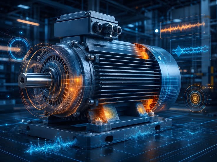
Induction motors are widely used in industrial applications, including manufacturing plants, agricultural machinery, water pumping systems, conveyor belts, compressors and automated production equipment. These motors operate continuously and play an important role in maintaining industrial productivity.
However, continuous operation, excessive load, poor maintenance and electrical disturbances can cause different motor faults. Common problems include bearing damage, winding failure, overheating, voltage imbalance, excessive vibration and mechanical misalignment.
Traditional motor maintenance often depends on periodic inspection or manual observation. These approaches may not identify developing faults early, potentially resulting in unexpected equipment breakdowns and increased maintenance costs.
An Induction Motor Fault Detection System Using IoT and Artificial Intelligence is designed to monitor motor operating conditions continuously, identify abnormal behaviour and provide early fault alerts.
The proposed project combines sensors, microcontrollers, IoT communication and machine learning techniques to develop an intelligent motor monitoring solution. It can help industries improve equipment reliability, reduce unexpected downtime and implement predictive maintenance strategies.
Key Features & Benefits
Objectives of the Induction Motor Fault Detection Project
The main objective is to develop an intelligent monitoring system that identifies abnormal induction motor operating conditions before they develop into serious failures.
Key project objectives include:
Monitor motor temperature continuously to identify overheating conditions.
Measure motor vibration to detect bearing problems and mechanical abnormalities.
Monitor voltage and current variations to identify electrical irregularities.
Identify abnormal operating conditions using threshold-based logic or machine learning.
Transmit sensor readings to an IoT dashboard for remote monitoring.
Generate alerts when abnormal motor conditions are detected.
Maintain historical sensor records for performance analysis.
Support predictive maintenance and reduce unexpected motor shutdowns.
Working Principle
The system operates by collecting real-time information from sensors connected to the induction motor.
Initially, vibration, temperature, voltage and current sensors collect operating parameters. A microcontroller such as ESP32 or Arduino processes the sensor readings and transmits the collected information to a server through Wi-Fi or another communication technology.
The server receives the sensor data and evaluates the operating conditions. A machine learning model can analyse historical and real-time measurements to classify motor conditions into normal and fault categories.
When an abnormal condition is identified, the system updates the dashboard and generates an alert for the operator.
The monitoring dashboard displays live readings, fault status, historical information and motor operating conditions.
Implementation Guide
Components Required for Induction Motor Fault Detection
The proposed system uses a combination of electronic sensors, processing hardware and software technologies.
Hardware Components
1. Three-Phase Induction Motor
The induction motor is the primary equipment under observation. Its operating conditions are analysed to identify electrical and mechanical abnormalities.
2. Vibration Sensor
An accelerometer such as MPU6050 or ADXL345 measures motor vibration along different axes. Abnormal vibration patterns can indicate bearing defects, shaft misalignment or mechanical imbalance.
3. Temperature Sensor
A temperature sensor such as DS18B20 or LM35 monitors motor surface or bearing temperature. Increasing temperature may indicate excessive load, insufficient cooling or winding-related problems.
4. Current Sensor
A current sensor such as ACS712 or an appropriate industrial current transformer measures motor current. Abnormal current patterns may indicate overload, phase-related problems or other electrical faults.
5. Voltage Sensor
A suitable isolated voltage measurement module monitors motor supply voltage and helps identify voltage fluctuations and imbalance.
6. ESP32 Microcontroller
ESP32 collects sensor measurements, performs basic processing and transfers information to the monitoring platform through Wi-Fi.
Software and Technologies
Arduino IDE for microcontroller programming.
Embedded C/C++ for sensor interfacing.
Python for machine learning development.
Flask for backend API development.
MySQL for storing sensor readings and fault history.
HTML, CSS, JavaScript or React.js for dashboard development.
MQTT or HTTP REST API for communication.
Scikit-learn or TensorFlow for machine learning-based fault classification.
The selection of components depends on motor specifications, measurement requirements, safety considerations and project budget.
Technical Specifications
Implementation Steps for the Motor Fault Detection System
The development process can be divided into the following stages.
Step 1: Motor Setup and Sensor Installation
Connect the induction motor to the test setup. Install vibration and temperature sensors at suitable monitoring locations. Use properly rated and isolated voltage and current measurement equipment.
Step 2: Sensor Data Collection
Interface the sensors with an ESP32 or another suitable controller. Collect motor operating parameters at regular intervals and validate the readings.
Step 3: IoT Communication
Configure Wi-Fi or MQTT communication to transfer sensor information to a backend server. Send the readings through an HTTP REST API if using a web-based monitoring architecture.
Step 4: Database Development
Create a MySQL database to store motor readings, timestamps, operating conditions and detected fault information.
Step 5: Machine Learning Model Development
Prepare a dataset containing normal and faulty motor operating conditions. Train a classification model using algorithms such as Random Forest, Decision Tree or Support Vector Machine.
Possible classification categories include:
Normal motor operation.
Bearing fault.
Overheating condition.
Mechanical imbalance.
Electrical abnormality.
Overload condition.
The model should be trained and validated using representative labelled measurements. Fault categories should only be reported when the available sensor data supports them.
Step 6: Dashboard Development
Develop a web dashboard that displays real-time motor parameters, graphical sensor trends, fault notifications and historical records.
Step 7: Testing and Validation
Test the system under different operating loads and controlled fault conditions. Compare the predicted fault categories against verified test conditions to evaluate detection performance.
Real-World Applications
The induction motor fault detection system can be adapted for several industrial applications:
Manufacturing industries for monitoring production machinery.
Textile industries for monitoring spinning and processing motors.
Agricultural industries for monitoring irrigation and water pumping motors.
Automotive industries for monitoring conveyor and assembly-line equipment.
Power plants for monitoring auxiliary motor systems.
Mining industries for monitoring heavy-duty motor equipment.
Food processing industries for monitoring continuous production machinery.
HVAC systems for monitoring ventilation and compressor motors.
By combining IoT monitoring with intelligent fault classification, the proposed solution provides a foundation for condition-based maintenance and industrial automation.
Conclusion & Next Steps
Advantages and Future Scope
Advantages of the Project
Continuous monitoring of induction motor operating conditions.
Early identification of abnormal vibration and temperature patterns.
Remote access to motor performance information.
Automated fault notifications.
Historical data storage for maintenance analysis.
Reduced dependence on manual inspection.
Better equipment monitoring and maintenance planning.
Flexible integration with industrial IoT platforms.
Conclusion
The Induction Motor Fault Detection System Using IoT and AI provides a practical approach to monitoring industrial motor conditions and identifying abnormal operating behaviour.
By integrating vibration, temperature, voltage and current sensors with embedded controllers, machine learning algorithms and web-based dashboards, the proposed system can support intelligent industrial maintenance.
This project is suitable for Electrical and Electronics Engineering (EEE), Electrical and Electronics Technology and interdisciplinary engineering applications. It also provides opportunities to explore embedded systems, industrial IoT, artificial intelligence and predictive maintenance.
Students and engineering teams can extend the proposed architecture into a working prototype based on their application requirements, available hardware and testing facilities.
Contact Details
Aislyn Technologies, Bangalore
Phone: +91 97395 94609
Email: info@aislyntech.com
Website: https://aislyn.in
Contact us today to start building your Embedded project in Bangalore with our expert support!

























.jpeg)


