ABSTRACT
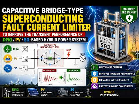
Fault current levels in land-based power systems are generally rising because of the increase in renewable generation capacity. Once the fault current level exceeds the capacity of the existing protection equipment, expensive upgrades become necessary. In order to avoid excessively expensive equipment upgrades, many fault current limitation techniques have been investigated. This work analysis the working of fault current limiters such as resistive bridge fault current limiter (RFCL), capacitive bridge fault current limiter (CB-FCL), capacitive bridge-type superconducting fault current limiter (CB-SFCL) to address the most concerning issue with the grid connected hybrid power system by improving the transient performance. The hybrid system comprises of a doubly fed induction generator (DFIG) based wind energy conversion system, a solar photovoltaic (PV) system and a synchronous generator (SG) based power system. The CB-SFCL possess a high temperature superconductor (HTS) along with a power capacitor to provide adequate reactive power support before and after the fault. The performance of the CB-SFCL is investigated by proper graphical and mathematical analyses and conclusions are obtained by comparing the working of the above mentioned limiters in different locations. The scheme offers several advantages: very fast-acting operation in response to faults anywhere on the system under study; maximum prospective fault currents are prevented from occurring, reducing the duty on circuit breakers; inherent, fast-acting backup; and communications is not required. It is shown that the scheme is suited to highly-interconnected systems with a high presence of DG. The scheme is readily applicable to the design of future utility and marine vessel power systems. The proposed system is simulated in MATLAB/Simulink software.
INTRODUCTION
The prospect of renewable energy sources (RESs) has become prominent after the inevitable downfall of the fossil fuels. Among the several RESs, the wind and the solar energy have been the most accredited choices due to their affordability, cheapness and reusability. Harnessing the wind energy has become so efficient and economical since the doubly fed induction generators (DFIGs) are employed in wind farms. The exclusive dual converter configuration of the DFIG allows it to operate during variable wind speed. Similarly, abundance of sunlight and decrease in the cost of electronic converters made the solar PV energy very popular choice over fossil energy. But, these RESs alone cannot fulfill the huge demand that the world needs daily. Hence, combining the RESs with some existing synchronous generator (SG) based power system has been the most acceptable solution to the power engineers. These hybrid systems are connected to the existing grid via a point of common coupling (PCC). Therefore, there are high risks that any kind of system abnormalities will affect the sources of the hybrid system directly, especially the DFIGs as their stator is directly connected to the grid. So, additional protection scheme is required to support the DFIGs and the overall system as per grid code. This, amongst other factors, may necessitate increased electrical network interconnection, which normally increases fault current levels. The connection of DG can also significantly increase fault levels and disrupt protection coordination. Furthermore, the fault current levels in power-dense marine vessel and aircraft power systems are inherently high. Safe network operation is very challenging in systems with a high fault level. Power system faults can cause significant damage—to life and to equipment—at the point of fault and to any equipment carrying fault current. Circuit breakers must be rated to clear faults for a particular system fault current level; higher fault currents lead to higher circuit breaker costs. There is a growing impetus for a “smarter” power grid, with ever greater reliability and efficiency. The future smart grid should: be built upon sustainable sources of power; allow increased network interconnects; allow flexible and adaptive networks; provide better management of power demand; incorporate an increased use of communications and standardisation for improved data sharing; and implement faster-acting power system protection. There are several barriers to this vision: ˆ Power networks need substantial growth, but also need a cost-effective way to delay or avoid significant upgrades. The prospective long life of power system assets leads to a largely expensive and static infrastructure. For example, for transmission network reinforcement, a 39 GW increase (a 50% increase) in UK generation capacity is expected to cost approximately £8.8bn. Consequently, National Grid Electricity Transmission is planning for capital expenses of £2-2.5bn per year over the next decade. Similarly large investments will be needed by distribution network operators, leading to an estimated £53.4bn total transmission and distribution investment by 2025. ˆ The UK has the ambitious target of an 80% CO2 emissions reduction by 2050 (relative to 1990 levels), and to achieve this goal significant DG using renewable sources of energy must be installed. Increased electrical system interconnection can improve the security of supply during periods of generation intermittency which are inherent for many forms of renewables. Increased interconnection also reduces transmission and distribution losses, supports the system voltage along the length of feeders, and provides greater flexibility in the use of available network capacity. Despite these benefits, a highly-interconnected power system will typically experience very high fault currents during faults, and faults can affect a greater area of the system. Furthermore, the coordination of protection can be difficult, expensive, or impractical for distribution networks with a high penetration of DG and for networks which are highlyinterconnected because ensuring proper coordination often requires communications for protection signalling. ˆ Full-electric marine vessels and aircraft have increasingly power-dense electrical systems, which leads to extraordinarily high fault currents. These compact, isolated systems are also particularly prone to the dangers of arcing faults and blackouts. ˆ There are several instances where circuit breakers in UK distribution systems are already over-stressed, which limits the network performance and flexibility, and prevents the connection of DG—including renewable sources. Therefore, higher fault levels can result in early obsolescence of existing circuit breakers, as well as incurring the replacement costs or other forms of network reinforcement. The size and weight of circuit breakers are additional constraints for marine vessel, aircraft, and offshore applications. Therefore, in many circumstances fault current levels are already high or are 3 expected to rise. Conventional methods of reducing fault currents, which include splitting busbars and increasing system impedance, have significant operational shortcomings, such as reduced security of supply for customers or increased system losses. There has been an increased need for technologies, such as SFCLs, which avoid these issues. Consequently, significant world-wide SFCL development, including several system trials, has been undertaken over the past decade, particularly in the UK, the USA, South Korea, Japan, Germany, and Italy. Nevertheless, SFCLs are a relatively new technology and network operators need to understand the best ways to use SFCLs. This thesis provides such guidance. In particular, this thesis highlights the challenges with using SFCLs, advises on key SFCL design decisions, and analyses the application of multiple SFCLs in electrical networks, including the relevant control and protection issues. Fault current limiters (FCLs) are one of the impeccable solutions that can provide sufficient protection in this regard. The FCLs vastly can either be superconducting or nonsuperconducting kind. The non-superconducting FCLs (NSFCLs) are easy to implement and their effectiveness have been validated in several literatures for standalone DFIG based wind farms, as well as wind farms connected to a hybrid system. However, they all comprise a fast fault detection (FFD) scheme which has to be accurate to get a seamless performance from the FCLs. Therefore, failing to provide a sound FFD scheme will be disastrous to the overall health of the power system. So, the use of superconducting fault current limiters (SFCLs) comprising high temperature superconductors (HTS) are gaining rapid popularity. The distinctive feature of the HTS is that they show different resistance for different levels of line current. For example, the HTS stays in superconducting state during the normal condition. At the instance of fault, the line current will rise and the temperature of the HTS rises as well. This modified state increases the resistance of the SFCL and suppress the fault current. Another advantage of the SFCLs with HTS coil is that they eliminate the necessity of any FFD scheme. The response time of the superconductors is significantly lesser than that of the non-superconductors. Use of the superconducting FCLs provides faster fault detection than regular over current protection schemes. Several SFCLs with HTS coils have been reported. However, the disadvantage of these SFCLs is that they are highly subjected to ac loss. Moreover, adjusting the current limiting resistance of the HTS is troublesome. To solve this issue, rectifier bridge type SFCL (BSFCL) was reported. The BSFCL has no issue with the ac loss as the fault current is rectified to dc before it is suppressed by the HTS. Also, tuning the resistance is easier with BSFCL as it can be easily done by changing the bias voltage. But, the BSFCL has the drawback that, it does not provide adequate reactive power support to the DFIG.
Block Diagram