ABSTRACT
In this, Voltage lift technique is used in electronic circuit design. This study presents the design of boost converter capable of providing boosted voltage for lower input voltages to drive the bldc motor. The classical buck converter for BLDC motor applications do not meet the load requirement containing more ripples on the output voltage and parasitic effects. In order to overcome this effect, the additional filter elements are added in the boost-converter to eliminate the output ripples and effectively enhance the output voltage level. The output stage of the boost converter is comprised of an inductor and capacitor so it naturally acts as filter. Also a battery energy storage system is used to store the excessive energy generated by PV source and it can be retrieved when PV source is not available. The output stage stores and delivers energy to the load and smoothens the output voltage to produce a constant output voltage. Thus this boost Converter is used for the proposed BLDC Motor Drive.
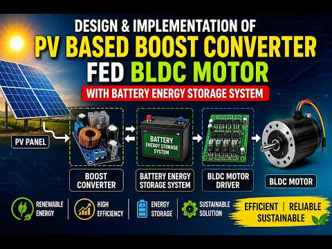
In this, PV panel is providing supply to the boost converter which operates based on the perturb and observe mppt and the inverter operates based on the reference speed of the bldc motor. The dc voltage is the function of the speed of bldc motor. Hence the dc voltage is changed according to the changes in reference speed. The converter output is provided to three phase inverter which converts dc to ac voltage and applied to the bldc motor. Also a battery is used to provide supply to the bldc drive when PV source is not available.
It is recommended to use it for high power applications. The PV source is connected to the boost converter. The boost converter consists of an inductor, a MOSFET, a diode and a capacitor. When the MOSFET is turned ON, the inductor gets charged and when the MOSFET is OFF, the inductor gets discharged and is in series with input voltage source and the output voltage is the sum of source voltage and inductor voltage. The output of the boost converter is provided as input to the inverter. It can be designed using by connecting three phase half full bridge converters. All three phase should be operate such that all of them should be 120 degree out of phase with each other. When the PV source is not available, the battery is connected through bidirectional dc-dc converter. The bldc motor runs in both modes and when both the sources are not available, the motor stops running.
Similar projects you might like