Introduction: Isolated Power Conversion in Multi-Rail Electronic Systems
Modern power electronic systems, ranging from industrial automation units to consumer electronics and medical devices, frequently require multiple regulated DC voltage rails (such as +5V, +12V, and -12V) derived from a single primary input source. Isolated DC-DC converters are essential to maintain electrical isolation between the high-voltage primary side and low-voltage secondary output circuits. Among isolated topologies, the Flyback converter remains one of the most popular and cost-effective choices for low to medium-power applications.
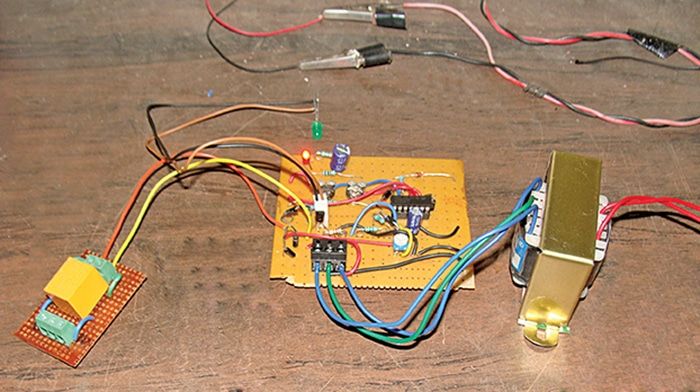
The Design of Voltage Mode Control for Multi-Output Flyback Converter project focuses on regulating multiple output DC rails using a single primary-side switching transistor and feedback control loop. Implementing Voltage Mode Control (VMC) involves sensing an output voltage rail, comparing it against a stable reference, and utilizing Pulse Width Modulation (PWM) to continuously adjust the power MOSFET duty cycle.
For Electrical and Electronics Engineering (EEE) and Power Electronics students, building and simulating a controlled multi-output Flyback converter provides essential hands-on experience in high-frequency transformer design, closed-loop feedback compensation, small-signal transfer function modeling, and hardware prototyping.
Key Features & Benefits
System Pipeline & Operational Workflow
The multi-output Flyback converter processes electrical energy and regulates output voltages through a multi-stage power conversion and feedback control loop.
The process begins with Primary DC Input & Energy Storage Phase, where an unregulated DC input voltage is applied across the primary winding of a multi-winding coupled inductor (Flyback transformer) when the main switching MOSFET turns ON. Energy is stored in the transformer core's magnetic field while secondary diodes remain reverse-biased.
Next, during Energy Transfer & Secondary Demagnetization Phase, the primary MOSFET turns OFF, reversing the voltage polarities across all transformer windings. The secondary diodes become forward-biased, transferring stored magnetic energy to the output filter capacitors and connected loads across each distinct output rail.
This advances to Voltage Sensing & Feedback Signal Acquisition, where the primary regulated output voltage rail is sampled using a resistive voltage divider and fed into an error amplifier circuit (such as a TL431 precision shunt regulator paired with an optocoupler for galvanic isolation).
Following this, Error Amplification & PWM Carrier Comparison compares the feedback signal against an internal reference voltage to compute an error signal. A analog or digital PWM controller compares this error signal against a high-frequency sawtooth ramp waveform to generate a variable duty cycle gate drive signal.
The system then enters Cross-Regulation Management & Output Stabilization, where the controller dynamically adjusts the MOSFET duty ratio to compensate for input line fluctuations and primary load shifts, keeping output voltages within tight regulation tolerances.
Finally, the system outputs Regulated Multi-Rail DC Power & Efficiency Evaluation, delivering stable, isolated DC supply rails to downstream electronic circuits while monitoring line/load regulation, efficiency percentages, and output ripple performance.
Implementation Guide
Key Features & Essential Technologies
Developing an isolated multi-output Flyback converter balances magnetic design parameters with precise closed-loop stability. Key features include galvanically isolated multi-rail DC outputs, fast transient response via Voltage Mode Control, optocoupler-based feedback isolation, snubber network protection against high-voltage inductive spikes, and high-frequency PWM switching.
The recommended technology stack relies on power electronics design and simulation tools. Circuit simulation and small-signal loop modeling are performed using MATLAB/Simulink, LTspice, or PSIM. Core hardware components include high-frequency ferrite core transformers (EE or EFD cores), power MOSFETs (such as IRF840 or CoolMOS), Schottky rectifier diodes, TL431 reference regulators, PC817 optocouplers, and dedicated PWM controller ICs (such as UC3842 or TL494). Hardware validation utilizes digital storage oscilloscopes (DSOs), programmable DC electronic loads, and isolation transformers.
Technical Specifications
Step-by-Step Implementation Guide for Students
Follow this structured step-by-step roadmap to design, simulate, build, and test your final-year engineering project:
Transformer Core Selection & Winding Calculation
Action: Calculate required core size, primary inductance, turns ratios, and wire gauges based on input voltage range, target output rail voltages, switching frequency (e.g., 100 kHz), and maximum output power ratings.
Verification: Calculate magnetizing inductance and verify that the transformer operates in the desired conduction mode (Continuous Conduction Mode - CCM or Discontinuous Conduction Mode - DCM) without core saturation.
Power Stage Simulation & Component Selection
Action: Build the open-loop converter circuit model in LTspice or MATLAB/Simulink. Select RCD snubber component values to clamp primary leakage inductance voltage spikes within safe MOSFET breakdown limits.
Verification: Run an open-loop simulation to confirm that secondary output voltages match design targets under rated load conditions.
Closed-Loop Feedback Controller Design
Action: Derive the small-signal open-loop transfer function of the Flyback converter. Design a Type II or Type III voltage-mode error compensation network using operational amplifiers to ensure adequate phase margin (greater than 45 degrees) and gain margin.
Verification: Perform AC frequency response analysis (Bode plot) in simulation to verify control loop stability and transient response speed.
Hardware Prototyping & Load Testing
Action: Assemble the physical converter circuit on a PCB or testing board. Wire the PWM IC, driver circuit, Flyback transformer, secondary rectifiers, and optocoupler feedback loop. Connect DC loads to each output rail.
Verification: Measure line and load regulation across all output rails using a digital multimeter and oscilloscope, confirming that output voltage ripple remains within design limits under varying load conditions.
Conclusion & Next Steps
Future Scope & Industry Applications
Isolated multi-output power supply architecture remains a foundational concept across numerous modern industries:
Industrial Control & Automation Systems: Providing isolated supply rails for Programmable Logic Controller (PLC) IO modules, gate drivers, and sensor networks.
Electric Vehicle (EV) Auxiliary Power Supplies: Generating isolated low-voltage DC rails from the main high-voltage battery pack to power auxiliary control electronics.
Consumer Electronics & Smart Appliances: Supplying isolated power to microcontrollers, display panels, and relay drivers from single-phase AC mains.
Building a Design of Voltage Mode Control for Multi-Output Flyback Converter project equips electrical and electronics engineering students with practical expertise in magnetics design, feedback loop control theory, power semiconductor switching, and hands-on hardware testing.
Contact Details
Aislyn Technologies, Bangalore
📞 Phone: +91 97395 94609
📧 Email: info@aislyntech.com
🌐 Website: https://aislyn.in
Contact us today to start building your Embedded project in Bangalore with our expert support!