Abstract
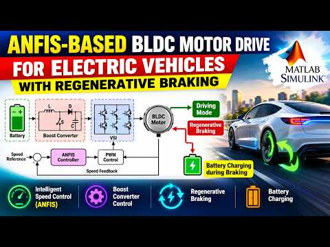
In this an electric vehicle system with BLDC drive powered with Battery is proposed. A boost converter is utilised for step up of battery voltage to motor voltage and a speed control technique based on ANFIS is also provided in this paper. The controller is tuned to reduce the speed error under various loading conditions. The simulation work is carried out using MATLAB/Simulink software. A simulation work is developed with regenerative braking for charging the battery during braking mode.
Key words—
Electric Vehicle, BLDC drive, Boost Converter, Voltage mode controller. Regenerative Braking.
I. INTRODUCTION
From decades, there are various drives applications wherethe induction motor is preferably used because of its differentadvantages like various speed control techniques, robustness,cost effective, availability in local markets, low maintenanceand service cost, availability in all ratings and capability ofoperation in risky/dangerous areas. But there are somelimitations of it, where the induction motor are not acceptablefor some special applications such as subjected to high heatingwhen supply voltage is too much low and complicated control,torque variations, integrations with renewable sources. Itfocuses the researchers towards a motor which will overcomeall these limitations of induction motor and give a bettersolution for drive applications. The brushless DC (BLDC)motors possess the features such as higher efficiency, highreliability, rugged in operation, simple control, lowerelectromagnetic interference, low maintenance, and operationat lower voltage range, higher torque to weight ratio andeffective performance for a wide speed range [1].The control scheme for BLDC motor which is usedconventionally and fed with an uncontrolled rectifier plus VSIshown in figure 1. In this scheme, pulses with high modulationfrequency (PWM) are used for switching of VSI which isfeeding BLDC motor. Because of these high frequencyswitching pulses of inverter, the large amount of switching losestaking place continuously at inverter switches. Also, thisscheme draws high value of harmonic current from the ACsource and which results in higher value for the THD index ofcurrent at source side with lower power factor [2].
Fig.1 Conventional Control of BLDC drive
The internationally accepted power quality standards like IEC61000-3-2 do not accepts such PQ issues at source side. The high switching losses and PQ problems at supply side are overcome by the proposed control scheme for BLDC motor with variable DC link voltage for VSI [4] . This utilizes the operation of inverter only for electronic commutation which is required for operation of BLDC motor at low frequency. ABLDC motor with a boost converter employing variable voltage for controlling requires a voltage sensor and speed sensor. BLDC motor with modified-Zeta converter, Luo converter, are proposed to control it in [5,6] respectively; but, these having the switches in series with the mains supply which results in increased interference problems and so it requires higher filtering.
Block Diagram
Software Requirements
1. MATLAB
2. Simulink
3. ANFIS Controller
4. Simscape Electrical / Power Systems Toolbox
Hardware Requirements
1. BLDC Motor
2. DC Battery
3. DC-DC Boost Converter
4. Voltage Source Inverter (VSI)
5. MOSFET / IGBT Switches
6. Hall Effect Sensors
7. Voltage Sensor
8. Inductor, Capacitor, and Diode
9. Regenerative Braking System