Your Cart

Your Wishlist

EXPLORE

Project Categories

9:30 AM - 6:30 PM | Call Us | WhatsApp

Chat with us Download App EEG Based Brain Controlled Wheelchair for Physically challenging person

DESIGN AND SIMULATION OF NINE LEVEL SWITCHED CAPACITOR MULTI LEVEL INVERTER

Category: Electrical Projects

Price: ₹ 5600 ₹ 8000 30% OFF

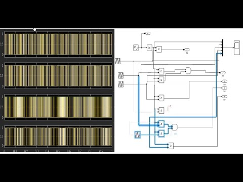
YouTube Video
Product Image

INTRODUCTION:

Electric vehicles, Flexible Ac Transmission Systems (FACTS),active filters, motor drives,other high-power conversion applications uses multilevel inverters (MLIs) as a superior power electronics solution. By creating stepped output voltage level waveforms, MLI attempts to simulate sinusoidal waveforms. In comparison to a traditional two-level output inverter, the MLI output voltage has higher power quality, lower total harmonic distortion (THD), better electromagnetic compatibility, and lower switching losses. Traditional MLIs come in three varieties. They are neutral point clamped (NPC), flying capacitor (FC), and cascaded H-bridge (CHB).In particular for generating higher voltage levels, NPC and FC MLI have difficulties as they require clamping diodes and capacitors, capacitor bank, voltage imbalance, etc.
CHBMLI stands out among these three topologies for its modular nature, which makes it simple to design, synthesise, and repair. Despite the knowledge of MLI topologies' widespread use, it is clear that CHBMLI require fewer components to produce the appropriate output voltage level and waveform quality compared to other MLI topologies. MLI is categorised as symmetric MLI and asymmetric MLI that depends on magnitude of dc sources. Another option for increasing the voltage levels is MLIs with hybrid construction. A hybrid MLI are made up of FC and CHB. However, using FC has apparent drawbacks because it necessitates of huge electrolytic capacitors and a difficult in control scheme to resolve the capacitor voltage balance issue.
The reverse voltage circuit topology is hybrid MLI. The fundamental component consists of two units: the first unit is the level generation unit, where it creates positive levels of output voltage. The polarity level generation unit, which can generate both positive and negative levels of output voltage is the other component. This topology combines both high and low frequency to obtain output voltage.
A new MLI topology for nine level is formed by switched capacitor and H-bridge is proposed in this paper. A symmetric MLI where dc sources value is same. In this topology output voltage can be same as the input voltage applied by connecting power switches in series and parallel. The capacitor charges and discharges to maintain voltage balancing. This topology utilize less switches to get desired output voltage. Furthermore, total harmonic distortion is reduced

Block Diagram

block-diagram

Related Projects

Similar projects you might like

Power Factor Improvement in Flyback Converter 0% OFF
Electrical Projects
Power Factor Improvement in Flyback Converter
(148)
₹8,000.00 ₹5,600.00
SSC Mitigation in DFIG Wind Farm Using Repetitive-PI & BESS 0% OFF
Electrical Projects
SSC Mitigation in DFIG Wind Farm Using Repetitive-PI & BESS
(384)
₹8,000.00 ₹5,600.00
Single-Phase Boost PFC Based On-Board EV Charger Project 0% OFF
Electrical Projects
Single-Phase Boost PFC Based On-Board EV Charger Project
(109)
₹8,000.00 ₹5,600.00
Fault Tolerant Controller Design for Pitch, Yaw and Roll of UAV 0% OFF