ABSTRACT:
Mixed-signal designs are becoming more and more complex every day. In order to adapt to the new market requirements, a formal process for design and verification of mixed signal systems i.e. top-down design and bottom-up verification methodology is required. This methodology has already been established for digital design. The goal of this research is to propose a new design methodology for mixed signal systems. In the first two chapters of this thesis, the need for a mixed signal design flow based on top-down design methodology will be discussed. The proposed design flow is based on behavioral modeling of the mixed signal system using one of the mixed signal behavioral modeling languages. These models can be used for design and verification through different steps of the design from system level modeling to final physical design. The other advantage of the proposed flow is analog and digital co-design. We have applied a mixed-signal simulator and AHDL to the top-down design of industrial ICs. The design process from the system-level down to gate/transistor-level modeling is developed in shorter design process cycles and higher rates of success. The proposed system is simulated in MATLAB/Simulink software.
INTRODUCTION:
In the past decades, power electronic converters are increasingly used as the grid interface for renewable power sources and energy-efficient loads. Despite the advantages of power converters in terms of high controllability and improved efficiency, various resonance and stability issues are also introduced by the interactions between wideband control dynamics of converters, passive power filters, as well as the grid impedance. It has been reported that the phase-locked loop (PLL) used for grid synchronization may bring a significant impact on the stability of the grid-connected converter, especially under the weak grid condition when the local voltage measured by the PLL is more influenced by the converter itself than by the grid voltage at the remote terminal. To effectively address these challenges, the impedance-based approach has recently been developed, which not only provides an intuitive insight of the interactions among the power converters but also enables to reshape output impedance for stabilizing the power system. With this method, a grid-connected converter, including the control system and the passive filter, is represented by a Thevenin/Norton equivalent circuit, where the output impedance/admittance allows analyzing the dynamic interaction between the converter and external grid/load impedance. In order to perform the stability analysis in different frames directly, different linearization methods are utilized to establish the impedance model of the converter, resulting in the dq-frame impedance model and the αβ-frame impedance model. The mathematical relations between the two models have recently been established, and it is revealed that all the models have the same stability implications. Since only the q-axis voltage is controlled for the phase tracking in the synchronous reference frame (SRF) PLL, the asymmetrical cross couplings between d and q axes in dq-frame impedance model, and introduce frequency couplings when the dynamics of PLL are included into the grid-converter interaction. Transfer matrices with cross couplings between the d- and q-axis components are needed for the stability analysis Due to the inherent asymmetry of the SRF-PLL, both the dq-frame and αβ-frame impedance models have to be represented by the impedance matrices to capture the asymmetrical dynamics. Consequently, the generalized Nyquist criterion has to be utilized for the stability assessment of this multi-input multi-output (MIMO) dynamic system. To facilitate the stability analysis and control design, some research efforts have been made to approximate the MIMO system to a single-input and single-output (SISO) system. However, only the symmetric MIMO system can be strictly represented by a SISO complex transfer function. Although the magnitudes of cross coupling components in asymmetric MIMO matrix are small in some cases, ignoring them can still lead to inaccurate stability implications. Moreover, the asymmetric dynamics of PLL characterized by the asymmetric MIMO matrix result in the frequency coupling effects in sequence domain, i.e., the one single-frequency perturbation imposed on the grid-connected converter will generate responses at two frequencies that are separated by twice fundamental frequency (2f1). This frequency coupling effect tends to introduce a sideband oscillation below the fundamental frequency, which can easily propagate in the power system and even trigger the sub-synchronous oscillations (SSO) together with the traditional power plant. It was reported that a low-frequency resonance in a wind farm resulted in the shaft torsional vibration protection and thereby the generator tripping in the thermal generation plant 200 km away. Therefore, the elimination of such a frequency coupling dynamic and the associated low-frequency resonances are deemed critical to the safe operation of the modern power system. Advances in very large scale integration (VLSI) technology allow the implementation of large and complex circuits on a single chip. However: due to this complexity: it is impractical to simulate a full chip at the transistor level in SPICE. Mixed-signal simulation and analog hardware description language (AHDL) enable a top-down design approach for today’s large mixed- signal ICs and shorten design cycles.
PROBLEM STATEMENT :
In this paper, we describe our approach to the mixed signal top-down design methodology including behavioral modeling with AHDL: transistor-level implementation: simulation and model optimization at various levels of accuracy. We have applied this method to the design of more than ten commercial mixed signal ICs with significant improvement of the design process. The effectiveness of the method is demonstrated on a hard disk drive read channel circuit containing A/D and D/A converters: a voltage-controlled oscillator and a gain-control amplifier.
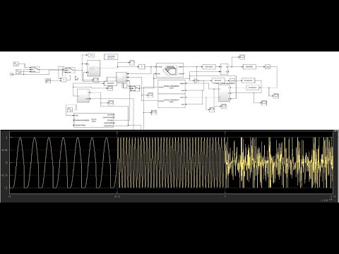
Block Diagram