ABSTRACT:
DC-DC converters are becoming increasingly popular in renewable energy applications and solar PV systems. This article introduces a non-isolated non-coupled inductor-based high-gain DC-DC boost converter with the desirable features of low voltage stress on controlled power switches and high voltage gain at lower duty ratios. The proposed converter is well suited for boosting the low-input DC voltage obtained from distributed generation units like photovoltaic (PV) or fuel cells to substantially higher DC voltage. The converter comprises only two switches, and a single PWM signal governs its operation. These characteristics result in a topology that is more compact, less costly, lighter weight, and easier to control. Fuzzy logic controller based voltage control loop is introduced for load voltage regulation under varying input and load conditions. The proposed converter is compared with conventional controllers across various performance parameters. The simulation is to be carried out in MATLAB/Simulink software.
INTRODUCTION:
The high-gain DC-DC boost converters are essential in converting small input direct current (DC) voltage ranging from a few volts to substantially higher DC voltage levels. These DC-DC converters must have a constant input current and step-up capabilities. Such converters are used in various applications like solar photovoltaic (PV) systems, robotics, high-voltage DC systems, and electric vehicles. The energy produced by sources like fuel cells or solar photovoltaic is quite low and the required output voltage is relatively high for various household and industrial applications. These pressing concerns enable the researchers to focus more on the development of high-step-up DC-DC converters. DC-DC converters consist of various arrangements of inductors, capacitors, diodes, and switches. These components are interconnected to enable energy exchange between inductors and capacitors. The process begins with the exchange of stored energy in the inductors. Subsequently, this stored energy is transferred to the capacitors, resulting in the achievement of a higher voltage level. In a DC microgrid, a high-gain DC-DC converter regulates the DC voltage to a specified level. Modern DC microgrids employ a combination of supercapacitors and a high-gain DC-DC converter. In the islanded mode operation of a DC microgrid, it is common practice to pair an inverter with a high-gain DC-DC converter to supply alternating current (AC) loads. High-gain DC-DC converters have increasingly become a popular alternative to traditional boost converters and their derivatives. The conventional DC-DC boost converter has some drawbacks. These include high voltage stress, upswing electromagnetic interference (EMI), intolerable input current ripples, and low efficiency at light load conditions and therefore it is unsuitable in practical applications where the duty ratio exceeds a predetermined threshold value. DC-DC converters serve as a bridge between the source and the load. These converters are generally categorized into isolated and non-isolated types. Conventional boost converters must operate at higher duty ratio values when integrated with microgrids. This results in a significant amount of current and voltage stress on the converter. As the duty ratio increases, the parasitic resistance (ESR) of the capacitor and inductor experiences a substantial rise, resulting in a significant loss in voltage gain and efficiency of the boost converter. Non-isolated converters are further classified as coupled inductor and noncoupled inductor-based configurations. An isolated converter creates electrical isolation between the input power supply and load. It effectively divides the circuit into two distinct sections to prevent the direct flow of current by incorporating a high-frequency transformer. However, it leads to an increase in both the size and expense of the converter. Isolated configurations are preferred in high-power applications that require a shared ground between the source and load. The coupled inductor configurations can achieve notably high voltage gain at a lower duty ratio but at a higher duty, it causes issues like switch voltage stress, conduction loss, low efficiency, and leakage inductance. This research article exclusively looks at non-isolated non-coupled inductor topologies. Non-isolated converters are preferred when there is no need for isolating the input from the output. To solve these challenges, various DC-DC converter topologies have been proposed in this article. The study proposed shows a comparative review of several non-isolated high step-up DC-DC converters. Several topologies of quadratic boost converter (QBC) have been introduced. These topologies are designed to produce significantly high voltage at lower duty cycles by effectively minimizing the stress on the switching devices, but at a higher duty ratio, the inductor core is more likely to saturate. A novel quadratic boost converter shown is designed to minimize the inductor current ripples and reduce the stress on the switches. The study proposed shows a quasi-z-source converter. This converter replaces the inductor with an impedance network belonging to the high-gain boost converter topology but they operate within a constrained duty cycle range. An interleaved boost converter presented enhances both output voltage and efficiency with fewer switches. A study proposed shows an interleaved high-gain boost converter carried out by combining two boost converters. The converter requires a large number of capacitors and diodes to achieve a higher voltage conversion ratio. A multiphase interleaved converter combined with a z-source network to achieve a high gain with a low input current ripple and eliminates the need for an input filter. However, a voltage boost circuit is required at the end of the converter to further enhance the converter gain. A quadratic boost converter is introduced by implementing the voltage lift technique. A high-gain hybrid converter uses a voltage multiplier cell and switched capacitor cells to mitigate the issues related to the stress on the power device. The study proposed shows a converter with different voltage stress levels on two switches. It employs both the diode voltage capacitor multiplier and switched inductor voltage multiplier techniques to attain high gain. The study proposed shows a non-isolated coupled inductor-based high step-up DC-DC converter with ultra-high voltage gain facilitated by an active switched inductor. The three-winding coupled inductor ensures a wide output voltage range for various applications. Its broad voltage gain range offers versatility, low semiconductor spikes to enhance reliability, and a simple gate driver control system to make it user-friendly.
PROBLEM STATEMENT:
In this, a novel topology of a non-isolated non-coupled high gain boost converter is proposed with fuzzy logic controller based load voltage regulation loop. The appealing characteristics of the proposed converter include:
• The proposed converter offers advantages including high gain, increased output voltage, and continuous current mode (CCM) operation. These qualities make it an attractive option for medium to high-power applications.
• The proposed converter offers a promising solution and achieves a high gain of approximately 16.67.
• The converter employs only two switches and the voltage stress on these power switches is lower than the output voltage. Despite having two switches it requires a single PWM signal for its operation which makes it easier to control and reduces the requirement for a gate driver.
• The absence of a coupled inductor eliminates the issue associated with leakage inductance and switch stress at a higher duty ratio. A performance comparison is made between conventional PI control and fuzzy logic control.
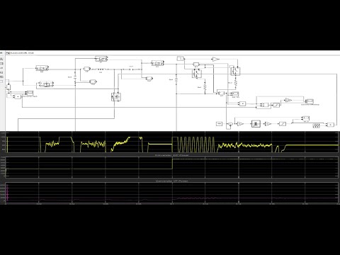
Block Diagram