ABSTRACT: The output power from a solar power generation system (SPGS) changes significantly because of environmental factors, which affects the stability and reliability of a power distribution system. This study proposes a SPGS with the power smoothing function. The proposed SPGS consists of a solar cell array, a battery set, a dual-input buck-boost DC-AC inverter (DIBBDAI) and a boost power converter (BPC). The DIBBDAI combines the functions of voltage boost, voltage buck and DC-AC power conversion. The BPC acts as a battery charger between the solar cell array and the battery set. For the proposed SPGS, the DC power that is provided by the solar cell array or the battery set is converted into AC power through only one power stage. The solar cell array also charges the battery set through only one power stage. This increases the power conversion efficiency for the solar cell array, the battery set and the utility. The battery set is charged/discharged when the output power of the solar cell array changes drastically, in order to smooth the output power from the SPGS. In addition, the DIBBDAI can suppress the leakage current that is induced by the parasitic capacitance of the solar cell array. The proposed power conversion interface increases power efficiency, smooths power fluctuation and decreases leakage current for a SPGS. The simulation work is carried out using MATLAB/SIMULINK.
INTRODUCTION
Extreme climate change has created global warming. In order to prevent irreversible climate change, the United Nations promotes the international convention on greenhouse gas emission reduction. Most countries are actively developing renewable power generation to reduce the environmental impact of greenhouse gas emissions. Renewable energy from solar energy and wind energy involves mature technology and is widely used to generate electricity. In the past, renewable power generation was expensive and depended on government subsidies but the cost of renewable power generation has decreased rapidly due to developments in manufacturing technology. The cost of renewable energy power generation in many countries is close to or less than the price of electricity that is generated using fossil fuels so an increasing number of renewable power generation systems are being integrated into the grid to generate electricity. The output power from a solar power generation system (SPGS) changes significantly due to environmental factors. These environmental factors change with the weather and seasons and cannot be controlled. As the penetration of SPGSs increases, drastic changes in their power generation will affect the voltage and frequency of distribution power system and can cause power outages. This reduces the power quality of distribution power systems. Several control strategies for the power conversion interface are used to alleviate the fluctuation in the output power from a SPGS. However, these control strategies only limit the increase in power from the SPGS by giving up maximum power tracking, and they only suppress the upward power fluctuations for the SPGS. In addition, the power that is generated by the SPGS is also decreased. To suppress upward and downward fluctuations of the SPGS, the rapid power regulation technology is required to temporarily store and release power to stabilize the power output from the SPGS. Since battery set has the advantages of small size, quick absorption and release of electrical energy and flexible operation, it has considerable potential as a power regulation device for the SPGS. In general, the control concept for smoothing the output power of SPGS is that the battery energy storage system supplies the difference between the average value and the instantaneous value for the output power of SPGS. The average value for the output power of SPGS can be calculated by low-pass filters moving average filters Saviztky–Golay filtering and moving regression filter. Since the instantaneous value for the output power of SPGS is rare equal to its average value, the charging/discharging time of the battery set is long. The output from a solar cell array is DC power and the battery set stores power in DC form, so a power conversion interface is needed for integrating solar cell array or battery set into the power grid for DC-AC power conversion. The configuration of SPGS and battery energy storage system can be divided into AC coupling and DC coupling. For the AC coupling configuration, the SPGS and the battery energy storage system (BESS) are respectively connected to the grid. Therefore, the SPGS and the BESS have their own DC-AC power converter and the circuit structure is more complicated. For the DC coupling configuration, the SPGS and the BESS share a common DC-AC power converter so the circuit structure is relatively simple. considerable potential as a power regulation device for the SPGS. In general, the control concept for smoothing the output power of SPGS is that the battery energy storage system supplies the difference between the average value and the instantaneous value for the output power of SPGS. The average value for the output power of SPGS can be calculated by low-pass filters, moving average filters Saviztky–Golay filtering and moving regression filter. Since the instantaneous value for the output power of SPGS is rare equal to its average value, the charging/discharging time of the battery set is long. The output from a solar cell array is DC power and the battery set stores power in DC form, so a power conversion interface is needed for integrating solar cell array or battery set into the power grid for DC-AC power conversion. The configuration of SPGS and battery energy storage system can be divided into AC coupling and DC coupling. For the AC coupling configuration, the SPGS and the battery energy storage system (BESS) are respectively connected to the grid. Therefore, the SPGS and the BESS have their own DC-AC power converter and the circuit structure is more complicated. For the DC coupling configuration, the SPGS and the BESS share a common DC-AC power converter so the circuit structure is relatively simple. each other. However, the output voltage has a higher peak value due to the DC offset. As a result, the voltage rating and the switching loss for the power electronic switches are increased. In addition, the Z-source DC-AC power converter and the boost DC-AC power converter cannot solve the problem of leakage current for the applications of SPGS. A buck-boost converter is integrated to the AC side of bridge architecture. The bridge architecture is switched in synchronous with the grid voltage to generate a square voltage, and the buck-boost converter is used to step up or down voltage and control the output current. The bridge architecture can be replaced by cascaded bridge architecture. The power electronic switches used in the buckboost converter should be bidirectional, which are composed of two conventional power electronic switches in series. The buck-boost converter can also be integrated to the DC side of bridge architecture. However, the power efficiency for the buck-boost converter is degraded because all of conversion power should be stored to and then released from the inductor. Moreover, these DC-AC power converters process only one DC power source.
Generally, the PV fed transformerless inverters suffer from leakage currents. To overcome the leakage currents the researchers have come up with numerous PV fed transformerless inverter topologies and control strategies. For example, grid-connected central or string inverter configurations consist of strings of PV panels which doesn’t require boost stage. However, the low voltage PV source requires a boost stage which reduces the efficiency of the system. Several researches have come up with the buck derived transformerless inverters which may not work during the low voltage PV source or PV source with shaded conditions. It is advisable to have transformerless inverter topologies with the buck-boost capability to have a wide operational range of PV sources. In this context, it can be understood that nowadays researchers have been showing more interest in proposing buck-boost based transformerless topologies. The authors proposed a buck-boost derived transformerless inverter topology which suits for wide range operation of the PV system. But the disadvantage of this topology is that it requires two separate PV sources for each half cycle of the output voltage. A buck-boost based transformerless topology is also proposed, which uses only four power switches and two input inductors. In this topology, each input inductor operates in either positive or negative half cycles which may lead to DC current injection. Another disadvantage of this topology is that the THD in current is more than 5% which is well beyond IEEE limits. The authors also proposed a buck-boost derived topology with a single input inductor and 5 switches. But this topology requires three extra diodes. Even though this topology has one single input inductor it requires a large input capacitor to track the maximum power from the PV source. Another disadvantage of this topology is that it has low voltage gain. The topology in can operate for a wide range of PV system. But it requires eight power switches and one single inductor. The higher switch’s count reduces the efficiency, reliability and increases the cost of the system. The proposed buck-boost derived topology reduces the switch count (i.e five switches). However, this topology requires larger input capacitance to track maximum point of solar PV. The topology also works for a wide range of PV system. In this topology, three switches conduct in every switching cycle which increases the conduction losses. Another disadvantage of this system is that it requires high current capability inductor which is large in size at the input which increases the system size, cost and reduces the efficiency. Further to reduce the switch’s count, researchers proposed a buck-boost topology with only two power switches. But this topology doesn’t have a symmetrical operation in both positive and negative half cycles of the output voltage. Another disadvantage of this topology is that the voltage across input PV should be greater than the required output voltage. Another topology was proposed in by using coupled inductor. This topology can provide high voltage gain at the output but in this topology also three power switches conduct during one switching cycle which increases the conduction losses and reduces the efficiency of the system.
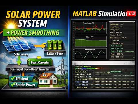
Block Diagram