ABSTRACT:
In this, an improved non-isolated high step-up (HSU) converter which consists of an inductor, a built-in transformer and a voltage multiplier is presented. The energy stored in the leakage inductance is recycled with the use of an active clamp circuit. The voltage stress on both power switches is also reduced, therefore, power switches with low resistance RDS,on can be used to reduce the conduction losses. The simulation is to be carried out in MATLAB/Simulink software.
INTRODUCTION:
The low voltage (LV) DC microgrids involving Photovoltaic (PV) generation, have been attracting an increasing interest lately due to the free-fossil energy source policy. Without extra arrangements though, the output voltage generated from a PV panel is slightly of low level, failing thus to meet the specifications of the DC microgrid. Therefore, a high step-up (HSU) converter is required to boost the low voltages to a voltage range of 380-400V. The use of the Coupled Inductor (CI) technique on the conventional step-up topologies was proposed. Ideally, the CI converters can provide extremely high DC Voltage gains in addition with low voltage across the switch, by simply increasing the turns ratio of the CI. Unfortunately, due to the nonperfect coupling coefficient K, the simple CI step-up converters for power levels around 250W can operate efficiently for Voltage gains only up to 11. At a later stage, in order to increase furthermore the DC Voltage gain, novel CI Voltage multiplier (VM) Boost converters were presented. However, in order to achieve Voltage gain levels higher than 20, the turns ratio must be selected at least 5. But in CIVM-Boost converters in contrary with the simple CI ones, the windings of the coupled magnetic component conduct simultaneously during all the switching period Ts. Thus, as the selected turns ratio increases, the primary winding current of the CI increases as well, due to the reflected secondary current. In order to reduce the conduction losses, the primary winding must become much thicker, resulting therefore in a voluminous and high cost coupled magnetic component. Thereby, the CI technique after a certain point is ineffective. In order to confront the aforementioned drawback of the CI, the technique of the built-in transformer (BIT) was proposed. The CI of the simplest CIVM-Boost topology is replaced by an inductor, and a transformer. In this case, because the average magnetized current of the BIT is null, the current of the primary winding is much lower. Thus, the primary winding and the magnetic core of the transformer result smaller than the CI ones. Thence, it is feasible to build a lower price, more compact and more efficient coupled magnetic component with greater flexibility in increasing its turns ratio. Recently, to achieve higher step-up ratios, the BIT in addition with the VM cell technique was applied on the topology of the coupled Modified-Sepic (MS) converter. Therefore, new BITVM-MS based converters with higher step-up ratio were proposed. Still, their Voltage gain compared to that of the CIVM-Boost converters is lower.
PROBLEM STATEMENT:
In this, an improved BIT-VM-Boost converter based on a specific CI-VM-Boost converter is proposed. This CI-VM-Boost based converter, ideally can provide Voltage step-up ratios almost equal to the CI-VM-Boost converters. But the absence of the clamp network, forces the leakage current of the CI to flow through the switch, decreasing substantially its efficiency. At first, by adjusting an active clamp circuit, the leakage energy is successfully recycled and zero-voltage switching (ZVS) is achieved for both transistors. Furthermore, the voltage spike across the of the diodes due to the reverse recovery (RR) procedure is eliminated. But even with this technique, for gains above 15, the CI component results very large and its primary winding suffers from high conduction losses. The solution to this problem is given by applying the built-in transformer technique, achieving thus a smaller and more efficient coupled magnetic component. With the proposed ZVS-BITVM-Boost converter higher DC Voltage gains than the BITVM-MS based converters in can be achieved.
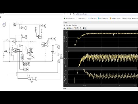
Block Diagram